Experimental Set-Up
Here you find information on each part of our experiment, with the different sections shown below. The experiment consists out of two main set-ups, designed to measure different properties of NFAL.
Near-Field Acoustic Levitation System
The common components of both set-ups needed to achieve NFAL.
Learn MoreHypergravity
Measurement

Set-up 1: Object displacement
The set-up to measure the equilibrium levitation distances.
Learn More
Near-Field Acoustic Levitation System
This constitutes the components needed to achieve NFAL in the first place, measure the environmental factors it is subjected to and ensure functional optimisation & integrity.
Levitation system
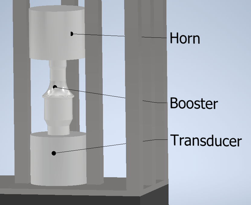
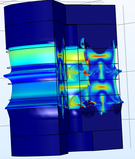
The levitation system consists of a transducer, booster and horn, connected in that order. The transducer, being the object to create the vibrations using piezoelectrics, is driven using a signal generator and amplifier and will be driven at 20 kHz with amplitudes between 1-25 μm with a maximum power output of 200 W. The booster and horn are there to amplify these oscillations and provide a uniform radiating surface acting on the body. We are currently developing our own transducer using COMSOL.
Frame & Damping
To be able to subject our equipment to 20G whilst also maintaining high levels of precision, a sturdy aluminium frame has been designed. One of the challenges here is to design it as such that parts of the different set-ups can be quickly interchanged to maximise our time-usage during our experiment campaign. Our frame is being developed in collaboration with our Physics Mechanical Workshop. To dampen any vibrations present in the LDC, we will be lining the bottom of the gondola with layers of Sorbothane, with different types for different G-ranges.

Environment meters
There are many parameters affecting NFAL, all of which need to be measured and accounted for. This requires us to have a barometer, thermometer, hygrometer & accelerometer. Additionally, whilst we will be minimising vibrations, we still require to measure the vibration profile so its affect on our data can be corrected for. Above you see an image of the effect of a temperature error on alpha, that being a variable in one particular theory, used to determine the resultant error in the force.
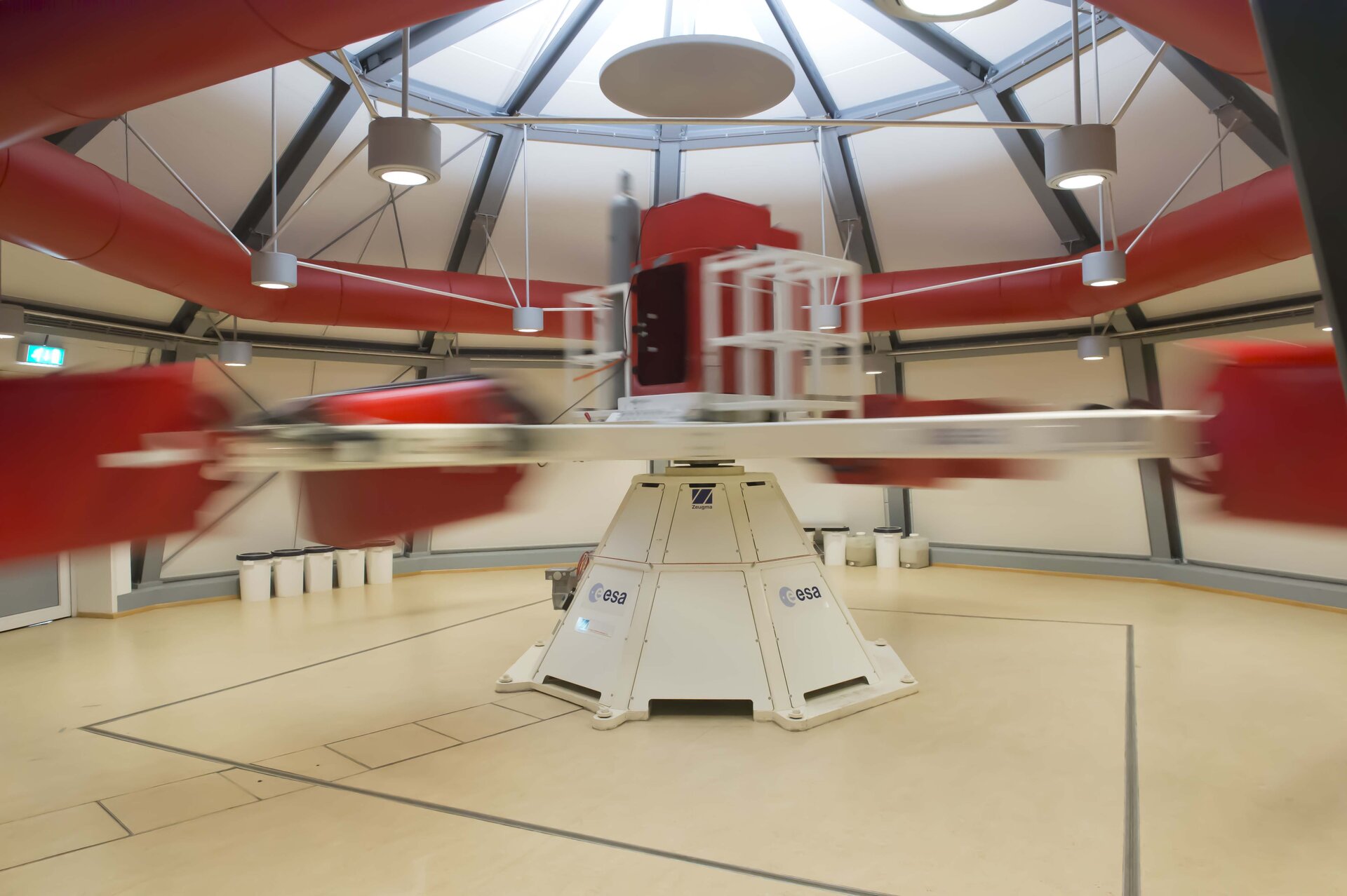
The Large Diameter Centrifuge
We will be making use of the LDC to simulate hypergravity up to 20 G. Using such equipment does also come with extra requirements for our set-up.
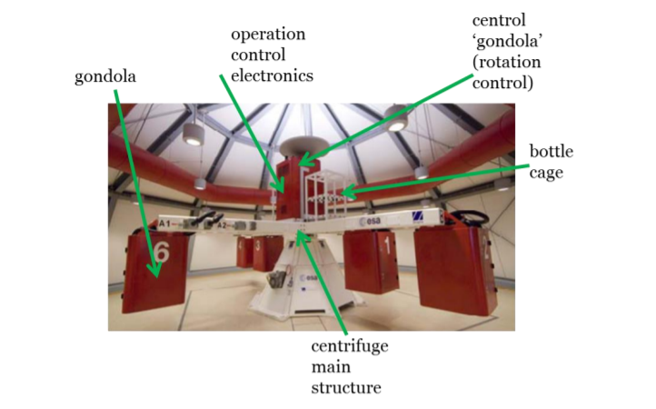
Gondolas & Control
Our experiment will be placed inside a gondola at the end of one of the arms. As such, it will be subjected to the restriction of max. 80 kg and a workspace of 500x500x720 mm. Whilst the experiment itself is subject to as high an acceleration as possible, the processing and control devices will be placed either in the central gondola or one halfway. From a control station, the equipment can be operated remotely, though automation is a priority.
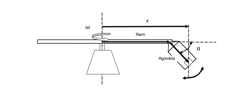
Force profile & vibrations
Though very close, artificially induced gravity is not perfectly uniform; the acceleration vector will be pointing slighlty outwards on the sides in the gondola and will be lower higher up in the gondola. Keeping our set-up centred and as low as possible is thus a goal to strive for. Furthermore, low frequency vibrations will be induced by components like the LDC motor and gearbox; this is a factor to consider given the micrometer range we are working in.
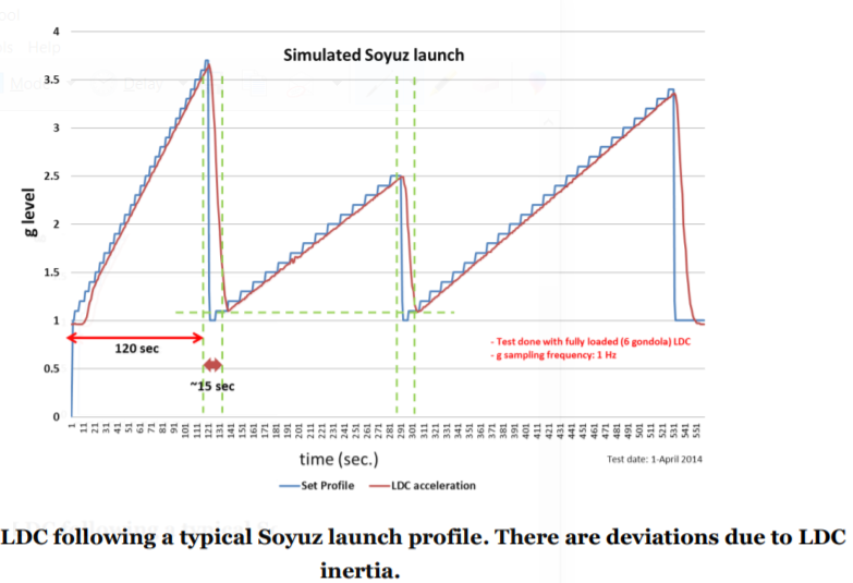
Gravity levels
The LDC is able to accelerate and deaccelate from 1 to 20 G in 60 & 55 s respectively and is able to provide us with a range of G-levels with small increments between them. Though we will only have 8 hours of experiment time per day, the LDC could theoretically run for 6 months straight.
For more information regarding the Large Diameter Centrifuge, see our Spin Your Thesis page
Set-up 1: Object displacement
The set-up investigating NFAL in particular, looking at the equilibrium position of free-floating objects as well as the presence & extent of resonance.
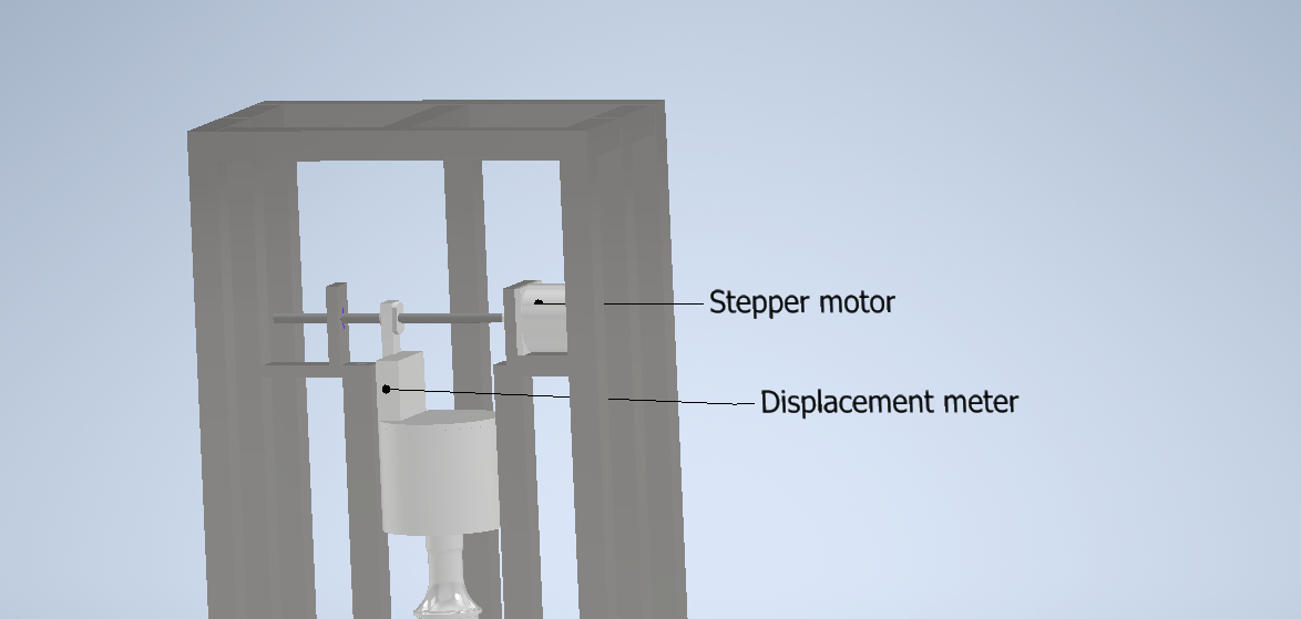
Displacement sensor
With an expected range of a few milimeter, we will be using a displacement meter with sub-micrometer precision and micrometer accuracy. The meter will be placed just above the levitating object to measure its levitation height as well as the amplitude of its resonance. Additionally, the meter will be used to measure the horn amplitude itself to obtain the radially symmetric displacement profile and calibrate the amplitude at different G-levels. The image above shows the set-up to be used in our own laboratories to obtain this profile.
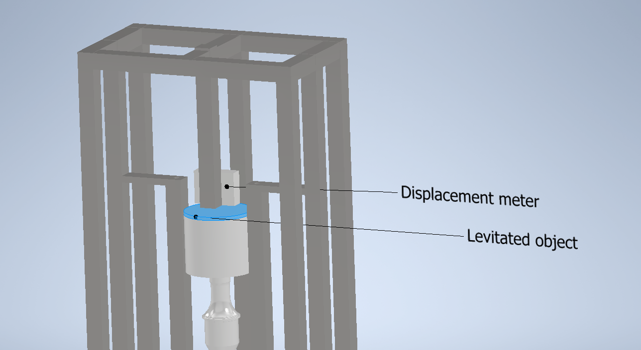
Levitated object
A homogeneous surface aluminium plate of around a milimeter thick is to be floated freely above the horn. The object is designed to reflect the acoustic radiation well, thus optimising the levitation force but also be light to allow for the fullest exploration of high G-levels whilst still enabling NFAL. Whilst the squeeze film provides a restorative centripetal force, a cage of wires is designed to be placed around the levitation system to provide a mechanical boundary. The image above shows the set-up as to be used in hypergravity. Note, the wire-cage is not shown.
Set-up 2: Force Profile
The set-up bridging the gap between NFAL and FFAL, investigating the forces as one moves away from the levitation system. Also, the attractive force, where it might be and how strong it is, will be investigated using this system.
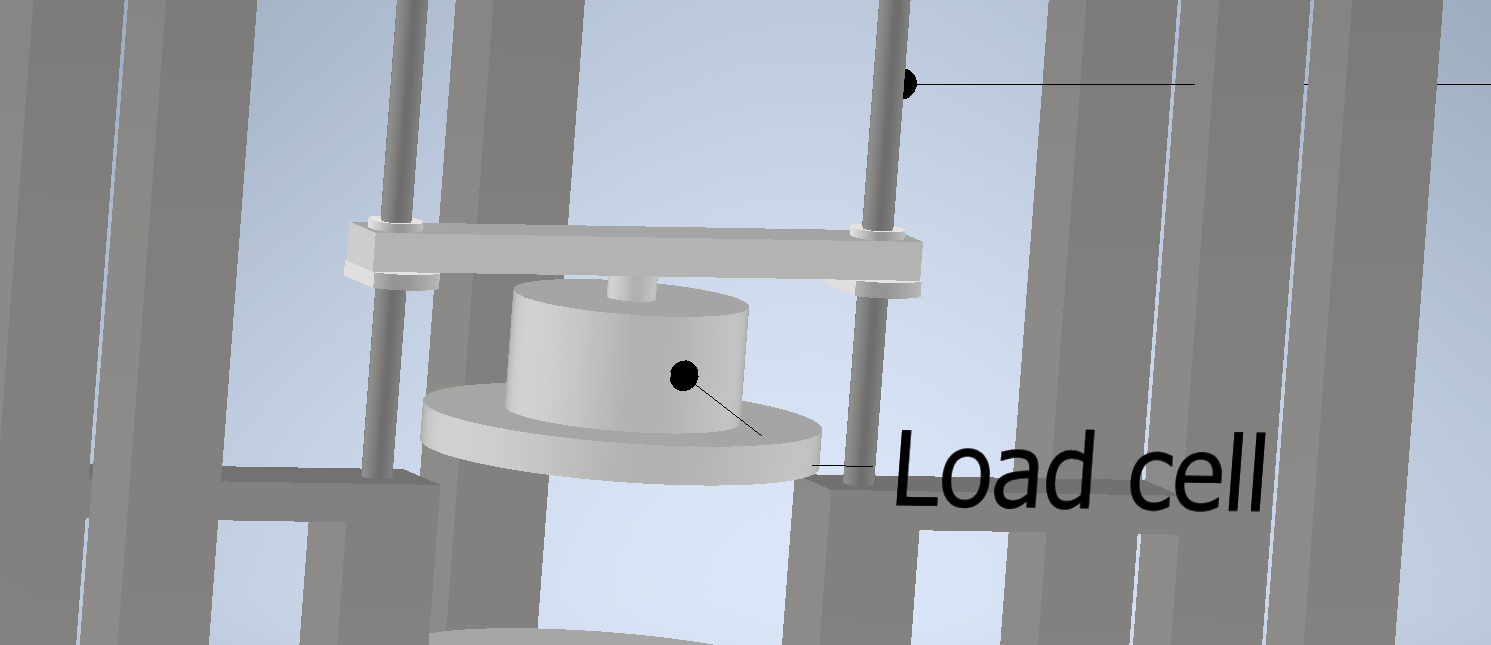
Force sensor
The force profile is expected to increase exponentially moving closer to the radiating horn surface. However, we expect peaks of a few Newton at integer multiples of half-wavelengths. The force sensor will be subjected to various effects to account for, including high baseloads, from the live mass, as we move up to higher G-levels, inducing creep; hysteresis caused by the connection of the electronics to the metal, temperature fluctuations and more. The system will be handling tension and compression based forces as we move through the force profile. The force sensor will be screwed onto a gantry above it and the "levitated" object below.
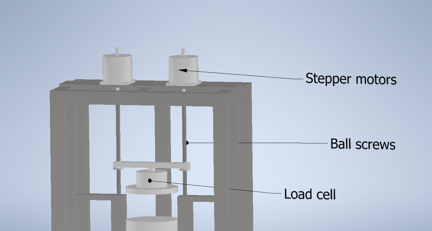
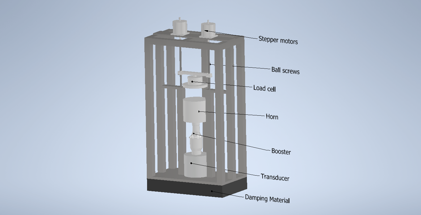
Linear actuator
A system of two stepper motors & ball screws will be used to precisely move the force sensor up and down. Sticking out from the top, holding the object through a gantry and supported on the bottom by bearings in support stands. We have chosen motors that give us micrometer stepsizes, with the possibility of going for smaller steps with microstepping due to the excess torque they provide. This system will be controlled using a stepper motor driver connected to a microcomputer, taking feedback from the force sensor.